The right mounting system for solar panels comes down to three decisions: where the array sits (pitched roof, flat roof, or ground), what loads the structure must resist (wind uplift, snow, seismic, and the dead weight of the modules), and which material will hold up for the life of the project. Get those three right, and installation becomes a matter of disciplined layout, correct fastening, and verification. Plan on a full day or more for a typical commercial roof section, with moderate difficulty and one firm prerequisite: a structural assessment of the supporting substrate before any rail goes down.
Systems fall into a few families. Rail-based racking suits most pitched roofs, ballasted frames avoid roof penetrations on flat membranes, and ground-mount structures offer the most freedom in tilt and orientation. Within each, aluminum extrusion has become the preferred material for professional installations. It resists corrosion without added coatings, weighs a fraction of steel, and can be extruded into custom profiles that integrate wire management, drainage, and module clamping in a single section. That customization matters on projects where a standard catalog rail won’t match the geometry or load path of the building.
Sustainability belongs in the selection too. Aluminum is highly recyclable, and a mounting structure that outlasts the modules it carries avoids a second round of material and labor at re-panel time.
This guide covers how to choose among system types, which tools and materials to assemble, the safety conditions that should stop work, a step-by-step installation sequence, and how to verify the finished array against applicable standards.
Types of Structural Systems for Mounting PV Solar Panels
Roof-Mounted Systems: Pitched and Flat Roof Options
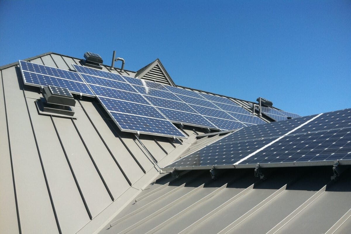
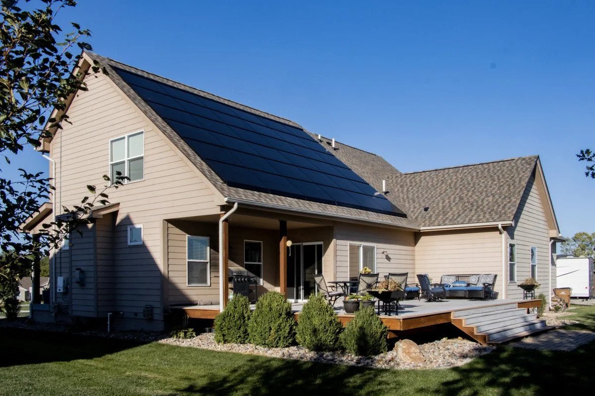
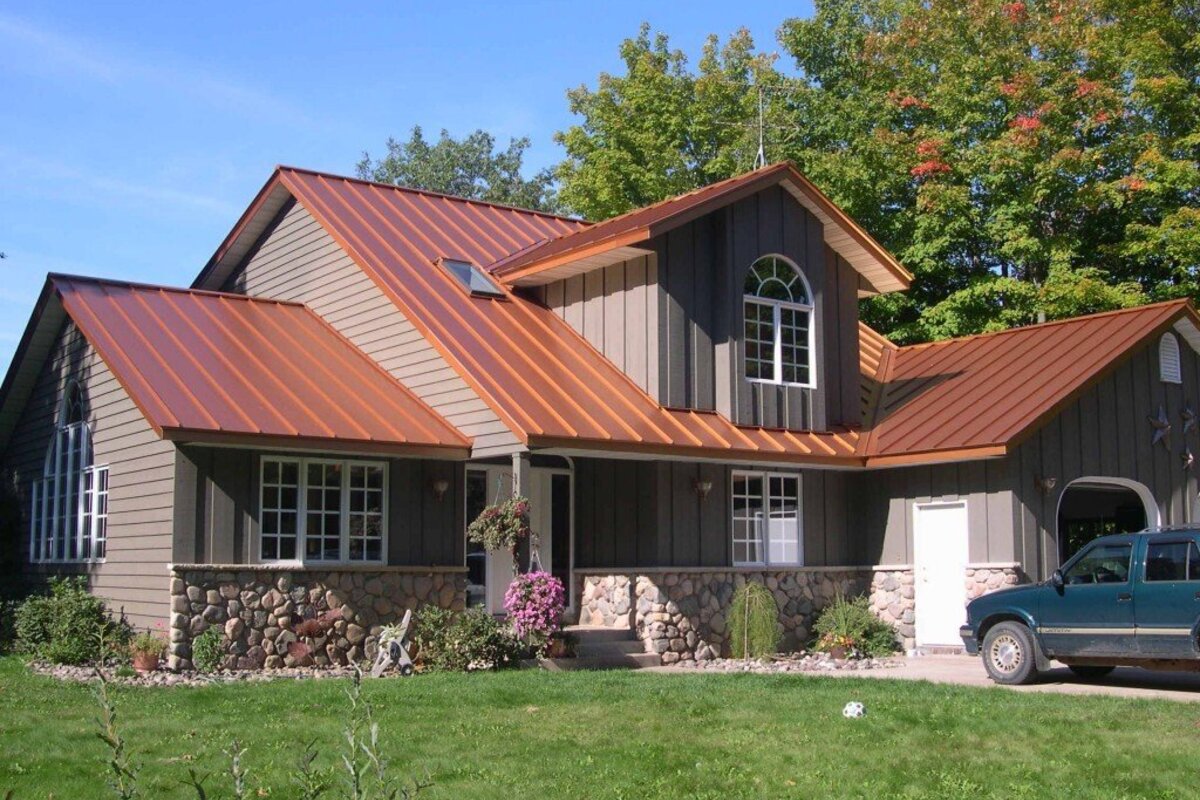
Pitched roofs typically use a rail-and-bracket approach. Brackets attach to the roof structure, rails span between them, and panels clamp to the rails. The bracket type depends on the roofing material. Tile hooks slide under or replace individual tiles and fasten to the rafters, keeping the tile layer intact. Standing-seam clamps grip the raised seams of metal roofs without drilling through the panel, which protects the weatherproofing. On corrugated or trapezoidal metal roofs, dedicated metal roof brackets seal against the profile and anchor into purlins or the supporting structure. In every case, fasteners must reach solid framing, not just sheathing, so locating rafters accurately matters.
Flat roofs call for a different logic. Ballasted racks hold tilted frames in place with weight, often concrete blocks, which avoids penetrating the membrane. They suit roofs with enough spare load capacity, but ballast adds dead load, so a structural check is essential. Where capacity is limited or wind exposure is high, anchored tilt systems fasten through the membrane to the structure below. Some projects combine both, anchoring the perimeter and ballasting the interior.
Waterproofing deserves attention in either case. Every penetration needs proper flashing and compatible sealant, and ballast trays should not trap debris or damage the membrane. Aluminum extruded rails and frames keep the added weight low, which helps preserve roof capacity. Their corrosion resistance also supports long service life across varied climates.
Ground-Mount and Carport Structures
Ground-mount systems are usually a fixed-tilt frame: rows of aluminum or steel rails carried by posts, set at an angle chosen for the site’s latitude and the array’s output goals. Foundations vary with the ground. Driven or screw piles suit many soils and go in quickly. Concrete ballast blocks avoid penetrating the ground, which helps on capped landfills or sites with buried utilities. Poured footings are an option where soil conditions or loads call for them. Single-pole mounts carry one small array on a central post and fit smaller or remote installations.
Carport and canopy structures raise the array on columns over parking areas, giving shade and weather cover alongside generation. Their longer spans and taller columns mean beam sizing, column spacing and drainage need careful design.
Site and soil drive nearly every decision. A geotechnical assessment should confirm bearing capacity, frost depth, groundwater and corrosivity before piles or footings are specified. Check slope, drainage, shading from nearby trees or buildings, and access for equipment. Wind and snow loads apply here just as on roofs, and span length affects profile depth and material use.
Ground systems are often preferable when a roof is shaded, structurally limited, near the end of its service life, or too small for the target capacity. They also give easier access for maintenance and freedom to set the ideal tilt and orientation.
Why Extruded Aluminum Profiles Suit Solar Mounting Structures
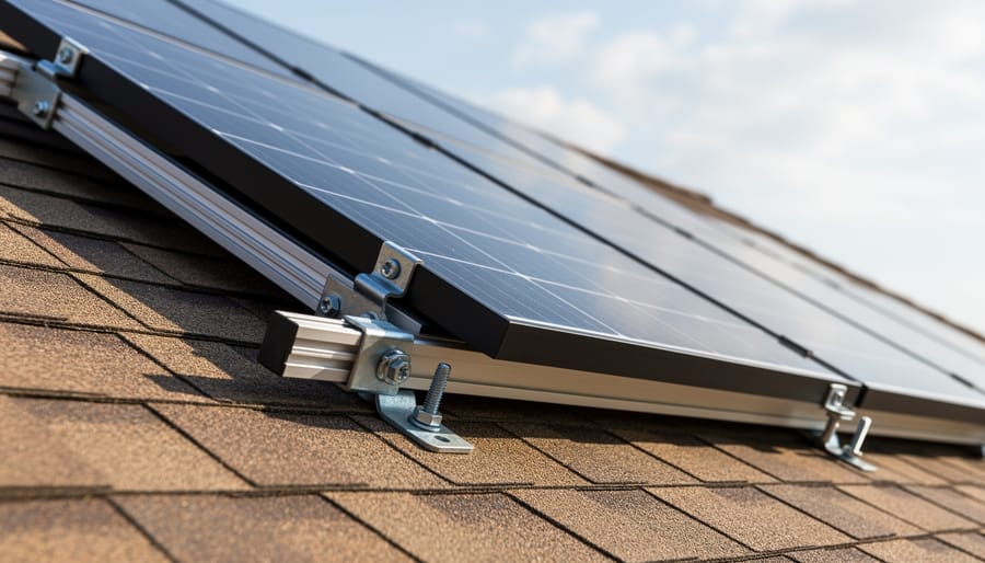
Aluminum earns its place in solar racking because the material’s properties line up with what a mounting structure actually faces: decades of weather exposure, repeated handling during installation, and the need to fit many different roof and ground conditions.
Corrosion resistance comes first. Aluminum forms a thin, stable oxide layer that protects the metal beneath, which is why it holds up outdoors without heavy coatings. Anodizing thickens that protective layer and gives a consistent surface finish, a useful option in coastal, industrial or high-humidity settings.
Strength-to-weight ratio is the second advantage. Aluminum profiles carry structural loads at a fraction of the weight of steel equivalents, so crews lift, carry and position rails more easily, and roofs bear less added dead load. Lighter components also reduce transport and handling burdens, which supports both safety and logistics.
The extrusion process adds design flexibility. A profile’s cross-section can include integrated channels for clamps, cable management features or bolt slots, so a single component does the work of several. When you choose aluminum profiles for a project, you can weigh standard sections against custom cross-sections, cut lengths and finishes specified to the array’s layout and load conditions.
Sustainability follows from these traits. A long service life reduces replacement cycles, and aluminum is readily recyclable at end of life. Quality management certification, such as ISO 9001, and in-house control from design through extrusion and finishing to delivery help keep dimensions and finishes consistent from batch to batch. Final performance still depends on the engineered design and the manufacturer’s documentation, so always verify specifications against your project requirements.
Choosing the Right System Before You Install: Planning Factors
Before you buy a single rail or bracket, confirm what your site can actually carry and withstand. Most mounting failures trace back to skipped planning, not poor installation.
Start with structural capacity. A pitched roof needs rafters or purlins in good condition, while a flat roof must handle added dead load from ballast or anchored racks. Review your roof type options early, because tile, standing-seam metal, membrane and shingle each call for different attachment hardware and waterproofing details. For ground sites, soil conditions decide whether piles, concrete footings or ballast make sense.
Next, define the environmental loads. Wind uplift and snow accumulation drive rail sizing, anchor spacing and foundation design, and both vary sharply by location and building height. Corrosion exposure matters too. Coastal, industrial and agricultural environments accelerate degradation, so material and finish selection, such as anodized aluminum profiles with compatible fasteners, should reflect the conditions the structure will face for decades.
Use this checklist to organize your decisions:
- Structural capacity of the roof, decking or soil, verified for added array load.
- Design wind and snow loads for your location and building height.
- Module dimensions, weight and frame thickness, which set clamp type and rail span.
- Tilt angle and orientation, balanced against wind exposure and energy yield.
- Corrosion exposure, including salt, chemicals and moisture.
- Code and certification requirements for the mounting hardware and modules.
- Customization needs, such as special profile lengths, finishes or integrated features.
Codes and certifications shape every item above. Load provisions such as IBC and ASCE 7 commonly govern structural design in many jurisdictions, mounting hardware is often evaluated to UL 2703 or an equivalent regional standard, and modules are typically certified to IEC 61215 and IEC 61730. Requirements differ by country, state and even municipality, so confirm what your authority having jurisdiction enforces.
Finally, know when to bring in a professional. Where codes require it, or whenever roof capacity, wind exposure or foundation conditions are uncertain, a licensed structural engineer should review the design and stamp the drawings. That review is far cheaper than a retrofit.
Tools and Materials for Installing a Solar Panel Mounting System
Before you start, gather everything in one place so the install does not stall mid-roof. Check that your components match the engineered drawings, and confirm profile dimensions and alloy against the supplier’s aluminum extrusion specs before ordering.
Mounting system components and hardware
- Rails or extruded aluminum profiles sized for your span and loads.
- Roof brackets, tile hooks, standing-seam clamps, or ground-mount feet.
- Mid clamps and end clamps matched to the module frame thickness.
- Splice connectors for joining rail sections.
- Stainless steel or otherwise aluminum-compatible fasteners and washers.
- Flashing, butyl tape, or approved sealant for every roof penetration.
- Grounding lugs, bonding jumpers, and wire management clips.
- For ground mounts, posts, piles, or concrete and ballast foundations.
Tools and test equipment
- Stud finder or rafter locator, chalk line, measuring tape, and level.
- Drill and impact driver with the correct bits and sockets.
- Calibrated torque wrench for clamps and bracket fasteners.
- Sealant gun for weatherproofing penetrations.
- Multimeter and grounding continuity tester, as applicable.
Material compatibility deserves particular attention. Dissimilar metals in contact, especially in damp or coastal conditions, can set up galvanic corrosion that slowly weakens connections. Choose fasteners and hardware that are compatible with aluminum, and use isolating washers or barrier tape where the manufacturer recommends them.
Finally, treat the manufacturer’s installation manual and the engineered drawings as the governing documents. They set torque values, clamp positions, and rail and bracket spacing for your specific system, and they override any general rule of thumb.
Safety Warnings and Stop Conditions Before You Begin
Before any panel or rail leaves the pallet, treat the site as a work-at-height and electrical job. Falls are the leading cause of serious injury in rooftop solar, so use guardrails or a personal fall arrest system anchored to a rated point, and set up a secure ladder or access platform. Keep the work area clear of loose tools and offcuts.
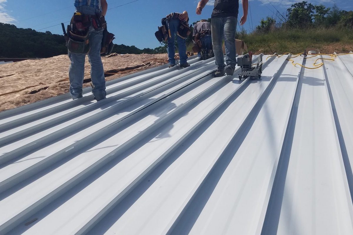
Electrical hazards are easy to underestimate. Modules generate voltage whenever light reaches them, so the array is never truly “off” in daylight. Keep panels covered or stored face-down until wiring is planned, and leave all connections to a licensed electrician who can isolate and verify de-energized circuits. If you plan to install on metal roof surfaces, remember that metal conducts and gets slippery quickly, which raises both shock and slip risks.
Large modules act like sails. Even moderate gusts can wrench a panel from your hands or push a worker off balance, so carry panels with two people and postpone lifting when wind builds. Wet, frosty or icy surfaces are equally good reasons to wait.
If site conditions differ from the design assumptions, such as softer soil, rotted decking or a different roof build-up than the drawings show, halt and request a licensed structural engineer’s assessment before continuing. Proceeding on guesswork puts people at risk and can compromise the array for its whole service life.
Step-by-Step: Installing a Solar Panel Mounting System
Layout, Marking and Anchoring
Begin by establishing the array boundaries on the roof or ground site. Mark the required setbacks from roof edges, ridges, hips and access pathways, using the dimensions shown on the engineered drawings and the fire and building code requirements of your jurisdiction. Snap chalk lines to define the outer edge of the array and the position of each rail run, then check the layout against the module count and row spacing before drilling anything.
Next, locate the structural members. On a pitched roof, use a stud finder or measure from known reference points to find rafters or trusses, and confirm their spacing against the design. On a metal roof, identify the seams or purlins that will carry the load. Mark every anchor point and verify the marks with a second measurement, since misplaced anchors are difficult to correct once the roof is penetrated.
Install anchors or foundations exactly as the engineered design specifies. For roof penetrations, apply the sealant, flashing or manufacturer-approved waterproofing at every anchor, and make sure the flashing integrates correctly with the roofing material. For ground mounts, set piles, piers or ballast to the specified depth, spacing and alignment, and check that each foundation is plumb and level before attaching any frame.
Rail Assembly, Alignment and Grounding
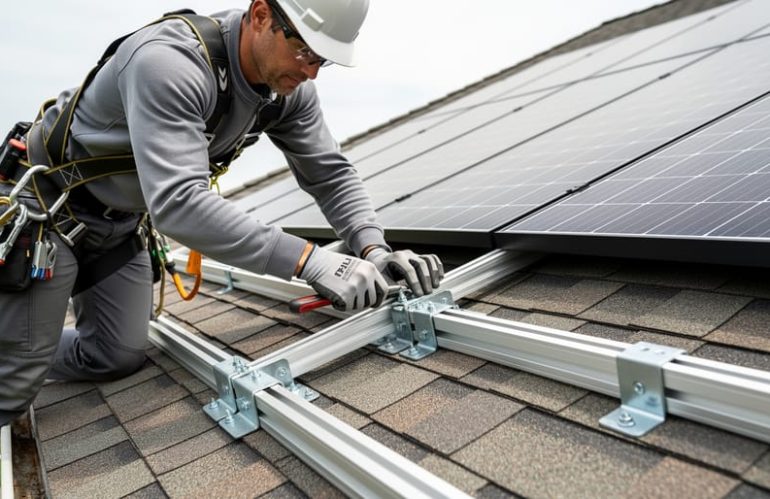
Once the anchors or feet are secure, attach the rails to them, working from one end of the array to the other. Start by snapping a chalk line across the anchor points so every rail follows the same reference. Fasten each rail to its brackets with the specified hardware, leaving the connections slightly loose until the rail is positioned, then tighten to the manufacturer’s torque values.
Check alignment before you commit. Use a level and a straightedge along each rail, and measure the distance between parallel rails at both ends so they stay square and match the module width. Shim at the brackets if the roof or foundation surface is uneven, rather than forcing the rail into position.
Where a run exceeds a single rail length, join sections with splice connectors. Leave the expansion gap the manufacturer specifies between rail ends, because aluminum expands and contracts with temperature and a rigid, gapless run can buckle or loosen its fasteners over time.
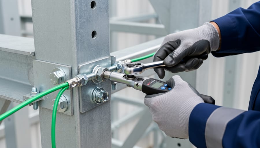
Finish with bonding and grounding. Install the specified bonding hardware, such as grounding lugs or bonding clips, so the rails and modules form a continuous electrical path. Connect it to the grounding electrode conductor following the applicable electrical code, and use components rated for contact with aluminum to prevent galvanic corrosion.
Panel Placement and Clamping
Once the rails are aligned and bonded, lift each panel into position with two people, keeping the frame level and clear of the rail ends. Wind catches large modules like a sail, so pause lifting in gusty conditions.
Place the first panel against the end clamp location and secure it loosely. Set the next panel beside it with a mid clamp between them, working across the row. Clamp zones are defined by the module manufacturer, typically a set distance from each corner of the frame, and clamping outside those zones can void the warranty or stress the glass. Check the module’s installation manual before every project, since requirements differ between models.
Tighten each clamp to the torque value in the clamp manufacturer’s documentation, using a calibrated torque wrench rather than an impact driver alone. Under-tightened clamps can loosen under wind load, while over-tightening can deform the frame or strip the fastener. Stainless fasteners paired with aluminum should be treated per the manufacturer’s guidance to limit galvanic corrosion.
Finally, manage the cables. Secure module leads with UV-rated clips or ties so they sit off the roof surface and away from sharp rail edges. Leave a small drip loop and avoid tight bends that could stress the insulation over time.
Verifying the Installation and Planning Next Steps
Before the array is energized, confirm that the structure is sound and compliant. Start with a visual inspection of every rail, bracket and clamp, then check fastener torque against the manufacturer’s specified values. Verify alignment and levelness along each row, and make sure expansion gaps at splices are intact. Review every roof penetration, flashing and sealant joint for gaps or missed coverage. Test grounding continuity across rails, clamps and bonding jumpers, and record the readings.
Keep the paperwork complete: as-built drawings, torque logs, photographs of concealed work and component certifications. Many projects bring in independent quality control specialists to audit this record before the authority having jurisdiction performs its inspection and approves commissioning. Requirements vary by jurisdiction, so confirm local procedures early.
Next steps matter as much as the handover. Schedule periodic inspections of fasteners, corrosion points, debris buildup and sealants, particularly after severe weather. If you plan further phases, work with a profile supplier early so custom cross-sections, lengths and finishes stay consistent across the whole array.
How often should the mounting hardware be inspected?
A common practice is an annual check, plus an extra inspection after storms or heavy snow. Follow the manufacturer’s maintenance guidance and local requirements.
Do I need an engineer’s sign-off?
Often, yes, especially for roof structures, high wind or snow zones, and ground foundations. Your building authority will confirm what documentation it requires.
Can mounting profiles be customized for unusual roof or site conditions?
Yes. Extruded aluminum profiles can be specified in custom cross-sections, lengths and finishes, subject to engineering review for the specific project.
Once inspections pass, file all records with the project documentation so future owners and maintenance crews can trace every component.
A solar array is only as dependable as the structure beneath it. A mounting system that is correctly specified, engineered for local wind and snow loads, and installed in the right sequence protects both the safety of the building and the long-term output of the modules.
The decisions that matter most are made early: matching the system type to the roof or site, choosing durable and recyclable extruded aluminum, and following applicable codes, certifications and engineered drawings. Each of these reduces risk over the decades the array will operate.
Projects with unusual spans, finishes or load conditions benefit from a manufacturer that can customize profile cross-sections, lengths and surface treatments rather than forcing a standard part to fit.
Your next step is to have a licensed structural engineer review the site, then discuss your project requirements with a qualified profile supplier before ordering components.